

ATMega microcontrollers are part of the 8-bit megaAVR family, based on the AVR architecture; they are among the most used microcontrollers, especially by hobbyists, since they are quite simple to use, also thanks to the widespread support of open-source tools.
In this article, we continue from where we left off earlier in a previous post here on antima.it, by starting to design a simple prototype board.
For this project, I am going to use an ATMega 644 MCU, since it is available in a through hole package, which makes it particularly easy to use on breadboards, by using a 9V battery to power it.
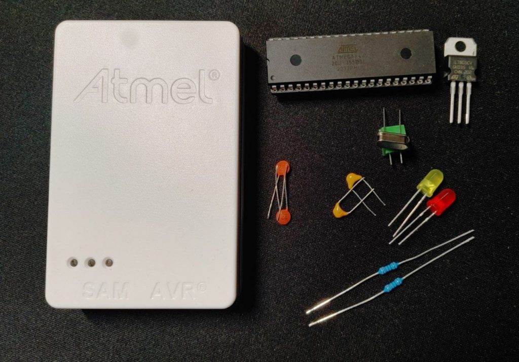
Components
- 1 ATMEGA644-20PU (64kB Flash, 2kB EEPROM, 32 I/O Pins)
- 1 DIP 40-pin socket, 2.54mm pitch
- 1 ATMEL-ICE
- 1 9V battery with a clip connector
- 1 L7805 voltage regulator, with an output of 5V
- Ceramic capacitors (0,1 μF, 0,33 μF)
- A couple of leds and resistors
Optional, if you want to have an external oscillator:
- 1 16MHz quartz crystal
- A couple of capacitors to use together with the quartz (12-22 pF)
Documentation
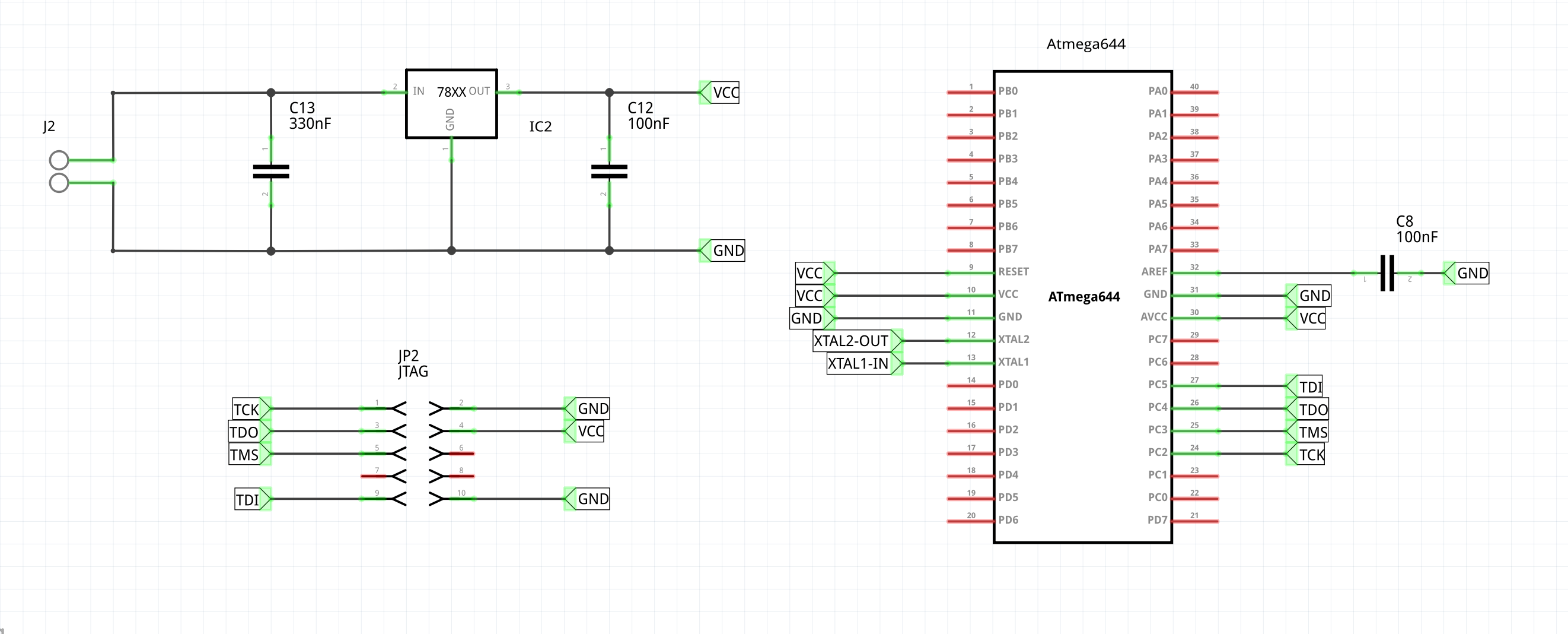
Here is is the complete circuit, to use as reference throughout the article:
The power stage
The ATMega644 must be powered with a voltage between 2,7V and 5,5V, like for all of the other microcontrollers in the ATMega series (with the exception of those with a part number ending with a ‘V’. Note that if you wanted to use the MCU with a frequency in the 10-20 MHz range, you would have to power it with a voltage between 4,5 and 5,5V.
Let’s consider this last scenario, so that there is nothing to change in the design phase in the case in which we would like to work with a frequency of 16MHz. In order to power the chip with the correct voltage starting from a 9V battery, I used a L7805CV voltage regulator from STMicroelectronics.
By consulting its datasheet, linked at the beginning of the post, it’s possible to see that the LC7805CV can work with an input in the 7-18V range, providing a 5V output. You can also find the recommended circuit to use it here:
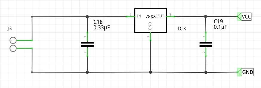
Powering this circuit will allow us to have a 5V output, which can be tested by connecting a resistor between VCC and GND and measuring the voltage over it.
VCC and GND can be connected to the microcontroller in order to power it , as shown in the first schematic included in this post. Note that AVCC and AREF gets connected to VCC and GND respectively, with a capacitor between AREF and GND. This configuration is the recommended one that can be found within the datasheet, when using the ADC with an internal reference (the ATMega644 can use a 1.1V or a 2.56V internal reference).
Connecting the ATMEL-ICE via JTAG
We can program the microcontroller through its JTAG interface, by using ATMEL-ICE programmer, which makes it possible to program and debug a plethora of AVR and ARM Cortex-M SAM chips. The programmer has two sockets in its lower section, with AVR and SAM written above them: always use the AVR socket when interfacing with the ATMega.
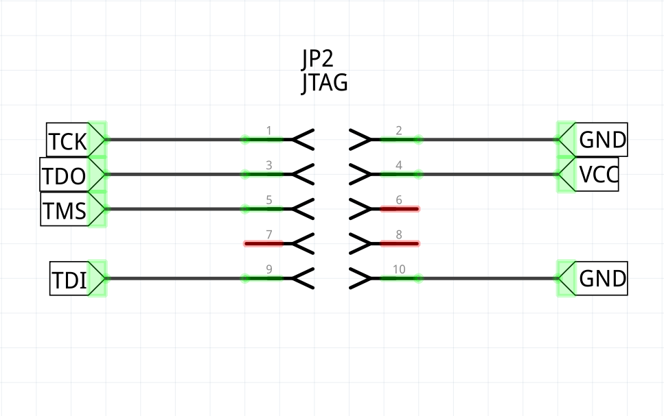
When connecting to the chip itself, we will use squid cable included in the ATMEL-ICE kit, which has every single jumper labeled with a number, where jumper number 1 is the red one.
You can use the following scheme to connect the cables to the microcontroller, remembering that the four target pins that you must use on the ATMega644 are the following ones: PC2 (TCK), PC3 (TMS), PC4 (TDO), PC5 (TDI).
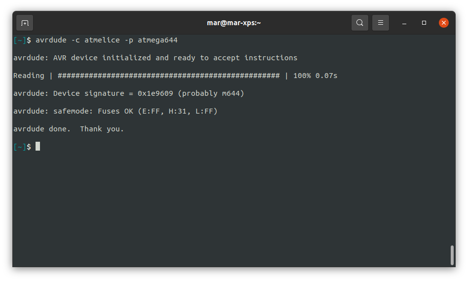
Now we can test everything out: let’s connect everything together and use avrdude to interface with the chip; you should have installed it by now if you read the previous post.
Once you connect the ATMEL-ICE to your computer, you can execute the following command:
avrdude -c atmelice -p atmega644
The application should answer back with some information, like the chip signature and its fuse values.
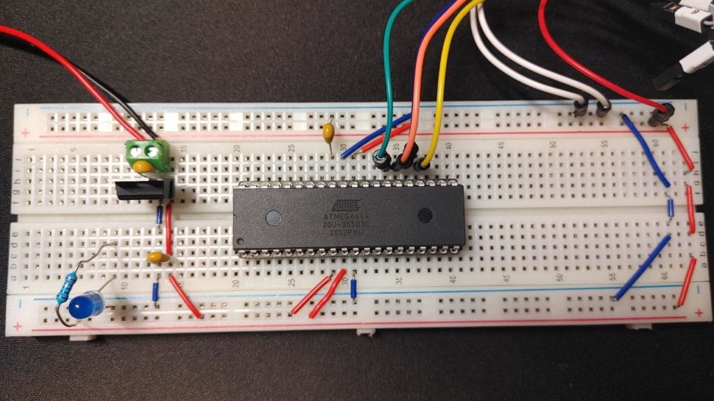
This is how your breadboard should look like if you followed everything up until now. I’ve added a blue led in the lower section of the board just to have some feedback that the power stage is correctly working.
ATMega fuse bits
Atmega chips have some special bits that can be used to configure some specific aspects of their inner working. These bits are organized in three fuse bytes: low, high and extended.
Getting the current value for each fuse byte is easy, you just execute the command we used a moment ago to test the connection to the chip. Be careful: programming these bits with an invalid configuration may brick your microcontroller, so always double check what you are doing.
The default values for the fuse bits in the ATMega644 are the following:
| Low | High | Extended |
| 0x62 | 0x99 | 0xFF |
Using an external oscillator
The ATMega644 has an internal RC oscillator running at 8 MHz that, in the default configurationm gets prescaled to a value of 1 MHz. In case you’d like to use a different configuration, you will have to change some fuse bits.
The specific configurations can be retrieved from the datasheet, depending on what you want to achieve; another tool that is really useful alongside the datasheet, is the Fuse Calculator website, that you can use to double check your fuse configurations.
AVR® Fuse Calculator
For example, when I use the ATMEL-ICE, iI tend to disable the SPI programming mode, and I almost always use a 16 MHz quartz crystal as an external oscillator. In that case, the configuration I would use is the following:
| Low | High | Extended |
| 0xFF | 0xB1 | 0xFF |
Which can always be loaded through avrdude:
avrdude -c atmelice -p atmega644 -U lfuse:w:0xff:m -U hfuse:w:0xb1:m -U efuse:w:0xff:m
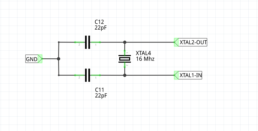
The circuit to set up in order to use the 16 MHz configuration can be found within the datasheet of the specific chip; I put a copy of the one for the ATMega644 in the picture below. Remember to following what’s inside the datasheet closely: in this case the capacitors should be in the 12-22 pF range, and both of them should have the same value.
Interacting with the microcontroller
Let’s write a simple program, so that we’re sure everything is working correctly.
Let’s open the template cloned in the last post, and change the frequency values in the CMakeLists.txt file (or in the Makefile if using make).
In case you’ve kept the default fuse configuration, then set the clock variable to a frequency of 1 MHz:
set(CLOCK_FREQ "1000000")
If you set up the 16 MHz external oscillator, then set it like this:
set(CLOCK_FREQ "16000000")
Blink
To test everything out, here is a simple blink program, that makes a led blink with a frequency of 1 Hz. The led must be connected to the PA0 pin, in series with a resistor.
If you followed the last post, you can paste the following code snippet inside the main.c file.
Otherwise, the whole blink project is available within our github page, at the following address: @github/antima/avr-blink. Note that this project is set up to work with an ATMega644, at a frequency of 1 MHz, using the atmelice programmer.
#include <avr/io.h>
#include <util/delay.h>

#define LED_PIN 0

int main(void) {
  DDRA = 1 << LED_PIN;
  PORTA = 0 << LED_PIN;
  for(;;) {
    PORTA ^= (1 << LED_PIN);
    _delay_ms(1000);
  }
}
Either way, once you’re done, execute the following commands:
mkdir build && cd build
cmake .. -B . -DCMAKE_BUILD_TYPE=Release
cd build/
make
make flash
Youu should see something like this:
Now that our small board is working perfectl, we can go on and create more complex applications, which we will do in the following posts of this series. We willexplore the ATMega peripherals and learn how to debug an embedded program.
That’s all for now, I hope you enjoyed the article and feel free to leave a comment below if you have any questions or want me to elaborate on any detail!